... or maybe PIC and pray!
Well, after my last post regarding the PIC microcontroller, I've got hold of a bunch more PICs (some from eBay, some directly from Microchip) and these include the relatively modest PIC16F648A of which I successfully bid on a tube of 25 for less than twenty quid, which I think is a bargain.The headline spec is as follows:
- 7Kb Flash program memory
- 256 bytes RAM
- 20MHz maximum speed
It also has 256 bytes of EEPROM, a capture/compare/PWM module, a USART, two comparators and a programmable voltage reference. The 7Kb program memory equates to 4096 instructions - because this PIC has a 14-bit instruction word - and the 20MHz maximum speed really means 5 MIPS because each instruction is executed in 4 clock cycles (20MHz / 4 = 5 MIPS).
The data sheet notes that this PIC "fits in applications ranging from battery chargers to low power remote sensors". So, I decided to do nothing of the kind .....
The Matrix
Ok, not this one ...

It has a single 8x8 matrix of LEDs, driven by a MAX7219 and hooked up to the microcontroller by a simple serial interface. You can address each of the 64 LEDs individually and make all sorts of fun patterns (really?), well that's what the blurb said when I bought it. You can also chain a few of them together, to drive something like a scrolling text display, which is why there is a five-pin header on the right hand side too.
Now driving this with the PIC instead of the Arduino would have been quite trivial. I could even almost copy the Arduino MAX7219 library and port it to C on the PIC. Also, 8x8 wasn't interesting enough and I didn't want to chain them, I wanted maybe a 2x2 block of these matrices, so I'd end up with a 16x16 array - big enough for something "useful" (ahem). Well, it's a learning exercise innit?
So, off to eBay again, and I picked up a few more LED matrices for about a pound each, and also a small stock of MAX7219's.
Circuit training
Now all I needed was a way to hook four of these together so I could drive the composite array with my PIC. The basic circuit was quite simple - sixteen lines from the MAX7219 to the LED matrix, a current limiting resistor and a couple of capacitors for smoothing and decoupling. Multiply by four, chain the MAX7219's together and you get something like this:
Now, the nice thing about designing this circuit using EAGLE is that it's easy to create a corresponding design for a custom PCB, just by dragging and dropping the components of your circuit onto a bare board layout. Ok, it's not quite that simple, but it's easy enough for a novice like me and I was keen to go through the process of designing a PCB and having it professionally made (which is actually unbelievably cheap, if you're prepared to wait for it to arrive from China).
Board? Me?
So, stumbling through the EAGLE tutorials and gleaning whatever advice I could understand from the Internet, I ended up with a board design like this:
I used EAGLE's auto-routing feature for the track layout - having never done this before and having little confidence that any changes I made would be "better", I just did my best to make it look pretty, exported the files in the generally accepted Gerber format, and sent the whole lot off to ITEAD Studio along with my £19 payment, and waited .....
... OK, I didn't have to wait as long as I thought. Eleven days later, my 10 (yes ten) boards arrived by air mail from China, and even to my unpractised eye, looked very good quality. See what you think :
 |
| Top view of the board |
 |
| Bottom view of the board |

... and then fitted all four of my LED matrices, one at a time:
 |
| One down, three to go |
 |
| All safely installed, if slightly untidy |
Slight deviation
While all of this was going on (i.e. the waiting part), I was busy preparing the PIC for the arrival of the super-matrix. Looking through my boxes of bits, I also found a 16x2 LCD panel, like this: |
| 16x2 LCD panel |
There are numerous examples of driving these LCDs, so I won't repeat the detail here. In summary, I'm driving it in 4-bit mode rather than 8-bit (saves 4 pins) and also doing this via an M74HC595 shift register, which means that - by doubling up on the shift register and LCD enable lines, I only use 4 pins in total from the PIC. I'm trying to save as many as possible to add more stuff later.
So, the final circuit for the PIC was as follows. Note the DIN, CS and CLK outputs that are destined for the 16x16 LED matrix assembly. The remainder is the LCD and its 595 driver, an ICSP header for programming the PIC in circuit, and an external crystal and load caps to get the PIC cranked up to 20 meg. Bottom right is a 10K trimpot to adjust the LCD contrast.

Happy days
Now, putting the whole lot together - with the PIC and LCD on a bit of stripboard, and some hastily written test code, we have lift off! ...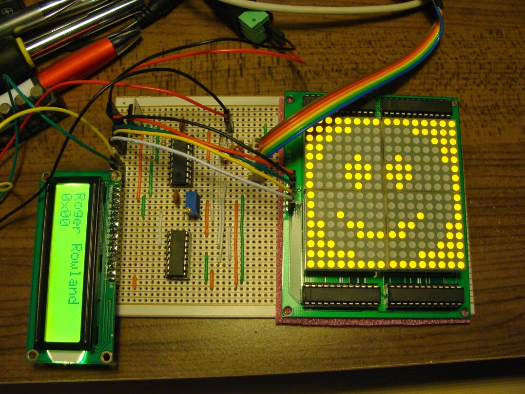
So far so good, but there was still a bit of capacity left on the PIC - I'd only used 50% of the 256 bytes of RAM and about 30% of the program memory. Not bad from the free (non-optimised) XC8 compiler supplied by Microchip. Also, I hadn't really done anything useful with the LED matrix other than flash up a hardcoded smiley.
So, back to the box of bits, and out comes an old (very old) PS/2 mouse. One with a real ball.
The final lap
Finally, with the help of this description of the PS/2 mouse interface, and a couple of my remaining PIC pins, I wired up the mouse and added the code necessary to initialise it and respond to its signals.I didn't show it on the schematic above, but the mouse connects to the PIC pins RB0 (mouse clock) and RB1 (mouse data). These pins are both used as open collector signals, so I have enabled the internal pull-ups on PORTB rather than use external pull-up resistors. It works well, and seems to be stable, which is all I could hope for.
So, now, at last, from that modest PIC, normally used for battery chargers etc., I'm supporting a 16x2 LCD display via a 595 shift register, a set of four MAX7219's each driving an 8x8 LED matrix, and a PS/2 mouse, that I have programmed to "draw" on the LED matrix. All in all, this would have been the starting point for an innovative arcade game thirty years ago (sigh - feeling old now), but it's taught me a lot - most of all it's taught me how little I still know and how much I'm enjoying this resurrected hobby ....
Take a look at the final video to see everything working together, and if you really feel inclined to do anything like this yourself, download the source code from here.
That's all until I've finished my next "project" - involving some of the more powerful PICs and a couple of (at least) wireless transceivers .... watch this space ....
PLEASE, WHAT DID YOU USE TO COMPILE THE SOURCE CODE TO HEX.
ReplyDeleteI used MPLAB X with the XC8 compiler. Download from http://www.microchip.com/mplab/mplab-x-ide
ReplyDeleteNice work
ReplyDeleteReally nice work
ReplyDelete