Once upon a time ...
So ... after messing around with that optical mouse a few months ago, I inadvertently rekindled my interest in a teenage hobby where, many years ago, I read every issue of Practical Electronics that came my way, bought numerous bits of Veroboard and burnt myself liberally with a cheap and nasty soldering iron, but really did nothing more than build other people's circuits and even then with just a handful of transistors etc. .... all of this digital logic was still quite new (we're talking mid 1970's here) and it was difficult to do anything really interesting without a lot more time and effort than I used to have back then .... not that I have much more now, of course ....Anyway, since my escapade with the mouse, I've been tinkering and reading and buggering about with a couple more Arduinos, and then, after posting a begging letter on Freecycle for any unwanted electronic components, somebody very kindly gave me, among other stuff, an 8-bit PIC microcontroller - a PIC16F676 to be precise - along with an old PICKit1 evaluation board, and this got me Googling and thinking ....
This was much closer to the metal than the Arduino, and being programmable in C as well as Assembler, felt like much more of a challenge!
So what did you do next?
What did I do? I'll tell you what I did .....I took some of the bits I'd been playing with on the Arduino - namely a handful of 8mm addressable RGB LEDs, commonly known as NeoPixels, and I decided to migrate one of the Arduino demo programs to the PIC.
Easy enough, I thought. But not after a closer look and a second thought. Or even a third thought.
These LEDs are really quite a package. Not just any old RGB LED, capable of displaying any of the 16.8 million colours familiar from normal computer displays, but they also contain the circuitry to latch in the last-set colour, so you don't need to keep pumping it with data from the microcontroller. They also have a neat one-wire communication method and can be daisy-chained together so that a single (albeit carefully crafted) pulse of 1's and 0's can set the colour of each LED in the chain and it will stay that way until switched off or told otherwise. So each LED needs only four connections: +5V and GND (to provide the power), the one-wire DATA_IN, and the similar outgoing DATA_OUT which feeds along to the next LED in the chain.
So, a simple daisy-chain of LEDs might be wired up like this (you can actually buy these same NeoPixels already wired on a metre long strip, or a ring, or various other shapes) ...

Hard times
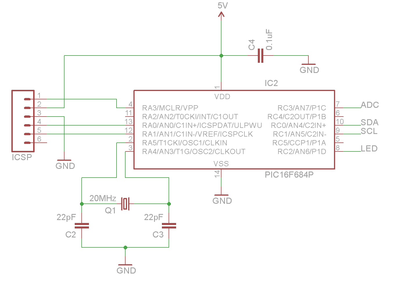
The downside to the handy one-wire interface, though, is the necessity to provide very tightly timed pulses. As there's only a single wire, there is no room for handshaking or any other common protocols. You must adhere to the datasheet specification, or it just won't work (although there is a bit of leeway and others have found that this can be stretched a lot further than first thought).Most of the mid-range PIC products can be clocked at a maximum of 20MHz by using an external crystal instead of the internal oscillator. With each instruction taking four clock cycles, this gives a minimum instruction time of 200 nanoseconds. The NeoPixel datasheets, with varying degrees of detail, specify that the shortest pulse - for sending a zero rather than a one - is somewhere around 350 nanoseconds (+/- 75ns) so with a couple of assembler instructions on the PIC it's just do-able.

The following code snippet is what I came up with:
I have 20 LEDs in my chain (because that's all I bought) and, as they can draw a maximum of around 60mA each when fully illuminated, they will need to have a suitable power supply, capable of supplying at least 1.2A (mine is actually rated at 2.5A, which is comfortably larger). Referring back to the LED circuit above, you'll also see a 1000uF capacitor across the power rails and a small series resistor for noise suppression as recommended by the LED datasheet.If you try to do this yourself, read the datasheet carefully, keep the power at 5V or lower (the LEDs have been reported to explode at 6V) and definitely add that 1000uF capacitor to avoid blowing your first LED at power-on.
You can see that I also added a handful of smaller bypass capacitors and an inline filter to keep noise to a minimum but these are possibly overkill. [UPDATE] I've now removed the inline filter and replaced it with an LT1086-5 voltage regulator and now take power for everything from this (it will supply up to 1.5A at 5V) so the schematic has been updated in the download.
Board (bored?)
On the image below, you can see the positioning of the PIC - notice I've used a different chip here, the PIC16F684 because the '676 doesn't have quite enough memory - and you can see the LEDs, which are wired in a boustrophodon pattern (Google it), all marked in yellow. You can see the LED power also marked, coming in from the middle left. The PIC and related circuitry has a separate power supply in this picture, which at that time came from my computer's USB (with grounds common). There is now a single regulated 5V supply (see update above).
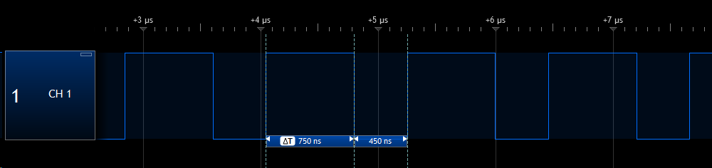
So, having got this far, it's useful to make sure that the code for driving the LEDs is performing in spec. Hooking up a logic analyser to pin RC2 on the PIC, and temporarily hacking the code to make it send alternate bytes of just zeros and ones (so each byte is either 0x00 or 0xFF), you can see that the timing is pretty much ok:
 |
| A section of a set of "zero" pulses |
 |
| A section of a set of "one" pulses |
"Like the corners of my mind ..."
Nice, but not very interesting. The Arduino NeoPixel examples have some nice colour-chasing effects and it would be good to replicate this on the PIC.The Arduino does this on the fly, calculating a new set of colours based on the elapsed time and the previous set of colours. Not so hard to do in C or C++, with floating point math support, but a different kettle of fish altogether using assembler on an 8-bit PIC.
So, cunning plan #1, why not use the Arduino code to generate a suitable set of data and then just hardcode that into the PIC?
Well, here's why not...
The Arduino is relatively well endowed when it comes to memory (the Uno has 2K), but the PIC16F684 only has 128 bytes (yes, bytes), and, given that I need 60 bytes (20 LEDs x 3 bytes RGB) for just a single set of colours, it limits the options somewhat. My first PIC, the 16F676 only has 64 bytes, which makes it totally impractical, but 128 bytes is still, well, not much.
Cunning plan #2 - add some more memory! Ok, more obvious than cunning, but at least another chance to learn a bit more and get some more interesting functionality into this putative project.
Microchip also makes a range of Serial EEPROM chips, like the 24LC64, which provides 8K bytes (64K bits) of additional memory.That's enough for about 130 frames of data for my 20 LEDs, and the memory itself is very cheap (I bought 10 of these from eBay for £3.64 including postage). It talks to the PIC using I2C, so only takes up two more I/O pins, one for clock (SCL) and one for data (SDA).
So this part of the picture goes like so:

It was easy enough to adapt the Arduino NeoPixel code and make it write 136 frames of colour data to the EEPROM instead of driving the the LEDs directly. Then all that's needed is to pop the EEPROM into the PIC circuit instead and write the code to read from it.
Mindreader
Some PICs have hardware support for I2C, but unfortunately, the 16F684 doesn't. However, Microchip have an Application Note - AN974 - that describes how to implement I2C in software to interface to a Serial EEPROM, which is just about perfect!All I needed to do was to adapt the example code for the EEPROM I used (this needs two bytes for the address rather than one), change the timing code to match my 20MHz clock and to run I2C at the faster rate of 400kHz, and put in the necessary infrastructure to load any of the 136 frames of data (each 60 bytes) into the PIC's memory to drive the LEDs.
Here's a very low quality snapshot of this part of the functionality in action - the colours don't get caught well on camera, so it's not (quite) as disappointing as it looks:

You can see the Serial EEPROM outlined in yellow, and it's associated bypass capacitor just partially obscured by the top left LED.
So far so good...
... but not quite good enough.So, trying to squeeze even more functionality out of the PIC, and noting that it has an ADC (analog to digital converter), and remembering even further back to when my mate Chris and I ran a disco when we were still at school, I thought I'd try to get some sound-and-light effects going.
At first, I didn't quite know how I was going to make this happen, but I did know that it would be possible to get some audio input from a cheap and cheerful microphone into the PIC via ADC and then do "something" with it in the software. That "something" would occur to me later, but for now, the final part of the circuit you can see at the bottom left of the board is this:

There's a 2.5V DC bias on the non-inverting op-amp input, to keep the signal from going negative (the ADC can't handle that) and the gain is set (experimentally) so that the output has a range of approximately 4V peak-to-peak.
Say what?
Ok, the audio input hooks into pin RC3 on the PIC, which is configured as an analog input (AN7). The ADC is 10-bit, which means a maximum range of 0 to 1023, so this maps my ~4Vpp to a range of around 0 to 800.Throwing away the two least significant bits gives me an 8-bit value in the range 0 to 200, which I can use to do that "something" I mentioned earlier.
The 0-200 number I end up with is just a very rough measure of the ambient noise level at an instant in time (well not an instant, but a very short period anyway), so it's not going to behave like a true peak detector from a sample-and-hold circuit, but it's possible to simulate the same sort of response in software. In pseudo-code, it goes something like this:
- Read the audio level from the ADC.
- If the level is greater than the current peak, store it in the current peak.
- Otherwise, decay the current peak by a small percentage.
This means that the peak will react quickly to increases in overall noise, but will decay more slowly if/when the noise level drops. This helps to average out the artefacts caused by sampling an alternating signal and in practice follows a sound quite well.
To avoid messing around with calculating percentages for decaying the current peak, I used more experimentation time to figure out that decaying by about 1% or 2% of the current value worked well with my overall time scheme. So, with my audio level ranging between 0 and 200, it was easy enough to hardcode this bit of logic to avoid unnecessary coding of 8-bit division:
- If the peak is greater than 140, decay by 3
- Else, if the peak is greater than 70, decay by 2
- Else, if the peak is non-zero, decay by 1
Seems simple, and it is, but works well and only takes a handful of lines of assembler code:

Nice but dim
Now, having got a number that sort of correctly follows the average sound level, I decided that the only "something" I could do with it was to use it to adjust the brightness level of the LEDs. So, the colours would stay the same as read from EEPROM, they would just be scaled down a bit dimmer when there is a low sound level.However, this required a bit of additional coding to get things happening at the correct time. There's no point reading the EEPROM and updating the LED colours too fast, because it doesn't look good and makes you feel sick. But, we do need to react to changes in sound level quickly or the whole thing will lag behind the live sound and that also won't be good.
Therefore, I've used one of the PIC's inbuilt timer modules to flag when it's time to read a new frame of RGB data from the EEPROM. I've set this so that the colours change about 9 to 10 times a second. When I've read all 136 frames, the code just goes into reverse and reads backwards to frame zero again, and so ad infinitum.
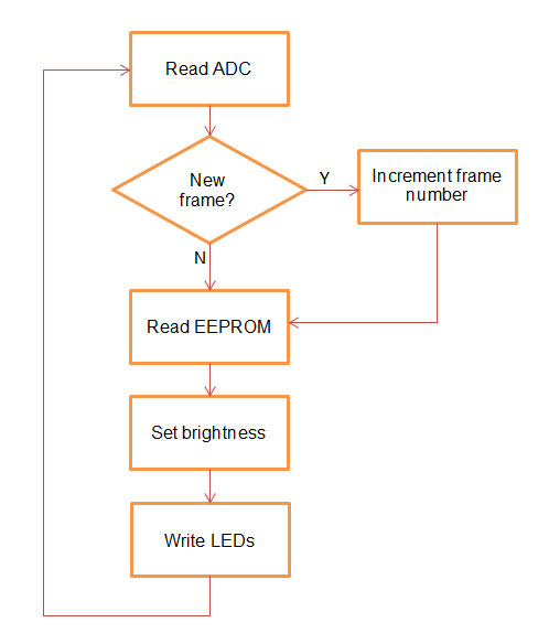
So, what happens when the colours are not changing is that the audio level is determined as already described, then the current frame of colour data is re-read from EEPROM and then adjusted in brightness according to the audio level before being sent to the LEDs. In simplified terms, like this:
The final curtain...
Right, that's enough explanation, you probably want to know what it looks like. Me too. It's just a shame that this sort of thing is very difficult to capture with video - colours are not good, focus shifts as brightness changes, etc. etc. but just so you get the feeling for it, here is version zero of my Totally Pointless Toy (TPT v0) ....One other effect I tried was to take an idea from this project, that simulates a fire effect using an 8x8 matrix of RGB LEDs. It's easy enough to just use the Arduino to write whatever I want to the Serial EEPROM and then just plug it back into my circuit. So, 136 frames of simulated fire later, this is the result ...
Source code
Right, that's all for this post - I certainly enjoyed myself and learned a heck of a lot in the process. If you want the source code and a copy of the whole schematic, you can download it from here.[Update]
After making some small changes, the board layout now looks as shown below, with an LT1086 5V 1.5A LDO voltage regulator supplying the whole circuit. This is a lot cleaner and just requires a single wall-wart power supply, which I robbed from an old Netgear router.